IoT Wizard
Navigation: Configuration > IoT Wizard
The IoT Wizard provides a guided, step-by-step process for setting up IoT data acquisition on the device. It walks the operator through selecting a data source protocol, defining a measurement, mapping data fields, and configuring a destination — all in a single linear workflow. The wizard is intended to simplify the initial setup when connecting the device to industrial field devices for the first time. For complex scenarios involving multiple sources, numerous metrics, or fine-grained control over polling intervals and serial parameters, the individual configuration pages under Configuration > IoT offer more flexibility (e.g., Modbus/RTU sources, Modbus/TCP sources, Metrics, Big-LinX IoT push).
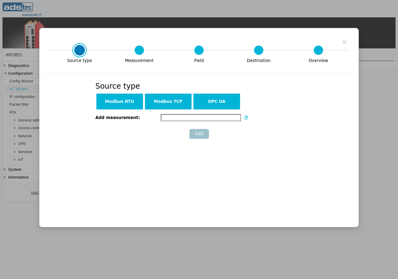
Steps
The wizard consists of five sequential steps. A progress bar at the top of the dialog indicates the current step: Source type, Measurement, Field, Destination, and Overview. Navigate between steps using the progress bar or the navigation buttons at the bottom of the dialog. Settings are applied collectively at the end of the wizard.
Step 1 — Source type
Select the communication protocol used to read data from the field device. Three options are available:
- ModbusRTU — Reads data from a Modbus slave device connected via the RS-485 serial interface. Select this option for devices that communicate over serial Modbus/RTU. The device must be equipped with an RS-485 port and physically wired to the slave device.
- ModbusTCP — Reads data from a Modbus/TCP server accessible over the IP network. Select this option for devices that provide a Modbus/TCP service on a TCP port.
- OPC UA — Reads data from an OPC UA server accessible over the IP network. Select this option for devices or PLCs that expose process data via the OPC UA protocol.
After selecting the source type, enter a name in the Add measurement field and click Add to proceed. The measurement name uniquely identifies the dataset in the IoT data structure and is used to identify data in Big-LinX.
Step 2 — Measurement
Configure the connection parameters for the selected source type. The fields displayed in this step depend on the protocol chosen in Step 1.
Modbus/RTU parameters
If ModbusRTU was selected, configure the serial communication parameters for the RS-485 bus. All parameters must match the settings of the connected Modbus slave device.
- Baudrate
- The serial baud rate for Modbus/RTU communication. Common values include 9600, 19200, 38400, 57600, and 115200.
- Data bits
- The number of data bits per serial character. Typical values are 7 or 8.
- Parity
- The serial parity bit mode: None, Even, or Odd.
- Stop bits
- The number of stop bits sent at the end of every character. Typical values are 1 or 2.
- Maximum read blocksize
- The maximum number of contiguous registers that can be read from this source in a single request. This value depends on the capabilities of the slave device.
- Poll interval
- The interval in seconds at which the configured registers are read from this source. A shorter interval provides more frequent data updates but increases bus traffic.
Modbus/TCP parameters
If ModbusTCP was selected, configure the network connection to the Modbus/TCP server.
- Hostname
- The hostname or IP address on which the Modbus/TCP device can be reached.
- Port
- The TCP port on which the device offers the Modbus/TCP service. The standard Modbus/TCP port is 502.
- Poll interval
- The interval in seconds at which the configured registers are read from this source.
- Maximum read blocksize
- The maximum number of contiguous registers that can be read from this source in a single request.
OPC UA parameters
If OPC UA was selected, configure the connection to the OPC UA server.
- Server URI
- The URL used to connect to the OPC UA server. The URI must follow the format
opc.tcp://hostname:port/. - Username
- Username for authentication on the OPC UA server. Leave blank to connect anonymously.
- Password
- Password for authentication on the OPC UA server.
Step 3 — Field
Define the data fields to be read from the source and map them to metrics. The available settings depend on the source type selected in Step 1.
Modbus fields (RTU and TCP)
- Metric name
- Identifies the field inside the measurement. Each metric name must be unique within the measurement.
- Register
- The Modbus register number, starting at 1. Note that some device documentation uses zero-based addressing. If the register address in the device documentation starts at 0, decrease the value by one when entering it here.
- Register type
- The data width of the register. A standard 16-bit Modbus register reads a single register. A 32-bit register reads two consecutive registers and combines them into a single value. A bit selection reads a specific bit from a 16-bit register.
- Modbus function code
- The function code used to read the register: read holding register (3) or read input register (4).
- Binary interpretation
- Determines how the raw binary register content is interpreted as a numeric value. The content can be cast into a signed integer, an unsigned integer, or a signed floating point type. Select the interpretation that matches the data format specified in the device documentation.
OPC UA fields
- Metric name
- Identifies the field inside the measurement.
- Namespace index
- The OPC UA namespace index. This identifier must be entered together with the node ID to unambiguously address the metric in the OPC UA model of the source.
- Node ID
- A numeric identifier within the namespace of the OPC UA source. Together with the namespace index, it unambiguously addresses the given metric.
Step 4 — Destination
Configure where the collected measurement data is sent.
- Activate IoT Push service
- When enabled, the selected measurements are sent to Big-LinX. This requires an active Big-LinX VPN connection configured on the Big-LinX page.
Note
The IoT Wizard currently supports Big-LinX as the destination for measurement data. For additional destination options such as MQTT, configure them manually on the Big-LinX IoT push or MQTT destination page after completing the wizard.
Step 5 — Overview
Displays a summary of all settings configured in the preceding steps. Review the source type, connection parameters, field definitions, and destination settings carefully before applying. After confirmation, the settings are written to the device configuration. To make the configuration persistent across reboots, save it via the Save page.
ATTENTION
The wizard creates new entries on the corresponding individual configuration pages (e.g., Modbus/RTU sources, Metrics, Big-LinX IoT push). If entries already exist on those pages, verify after completing the wizard that no conflicts or duplicate entries have been created.
Security
Only configure IoT data acquisition sources and destinations that are actively required for the intended use case. Each enabled source and destination increases the device's operational attack surface. Review the data being collected and transmitted to ensure that only intended process data leaves the local network. For Modbus/RTU sources, restrict physical access to the RS-485 wiring. For Modbus/TCP and OPC UA sources, ensure that the network path between the device and the field device is appropriately secured.