Layer 2
Navigation: Configuration > Packet filter > Layer 2
The Layer 2 tab configures packet filtering at the Ethernet frame level for bridged (switched) interfaces. While the main Packet filter page handles Layer 3 (IP) filtering between routed interfaces, this tab applies to traffic between interfaces that share a common bridge — for example, the LAN ports in transparent bridge mode, or the WAN ports when the WAN switch feature is enabled in IP router (extended) mode. Layer 2 filtering also applies to OpenVPN Layer 2 (TAP) tunnel interfaces when they are bridged with physical ports. The Layer 2 packet filter uses the same rule set structure as the Layer 3 filter, allowing fine-grained control over Ethernet frames based on MAC addresses and Ethernet protocols. Configure the operational mode and bridge assignments on the IP configuration page.

Settings
Packet filter Layer 2
The Layer 2 packet filter can filter all packets passing through the device on switched network interfaces.
The filter is based on a number of rule sets. Each rule set can contain up to 10 rules. A rule set is defined by its source and destination interface and its name. A rule contains all other detailed match properties such as protocol type and MAC addresses.
- Rule sets
-
The main area of the page displays all configured rule sets in their evaluation order. Each rule set shows its name, the number of rules it contains, and a brief description. Rule sets can be reordered using the up and down arrow buttons, edited using the gear icon, or deleted using the trash icon. The order of rule sets is significant: packets are matched against rule sets from top to bottom based on their source and destination interface.
Packets pass the packet filter from top to bottom. If a rule set's source and destination interface match the packet, the rules within that set are evaluated in order until a match is found. Processing stops at the first matching rule and the corresponding action is applied. If no rule within a matching rule set applies, the packet is passed to the next rule set. If no rule set matches at all, or no rule within any matching set matches, the packet is dropped.
- Add a new rule set
- Click the + button to create a new rule set. A new rule set requires a name, a source interface, and a destination interface. Once created, individual rules can be added to define match criteria and actions.
- Show rule sets for following interfaces
- Filters the displayed rule sets by source and destination interface. Use the from and to dropdowns to select specific interfaces, or leave both set to * to display all rule sets. This filter affects only the display and does not change the active configuration.
ATTENTION
The default policy is to drop all traffic that does not match any rule. When creating a new configuration, ensure that all required traffic flows are explicitly permitted before applying the settings. Applying an incomplete rule set may cause immediate loss of network connectivity, including remote management access to the device.
Security
Follow the principle of least privilege: allow only the specific protocols and address ranges required for your application and deny everything else. Review rule sets regularly to remove obsolete entries and verify that no unintended access paths exist. In accordance with IEC 62443, restrict traffic between network zones to the minimum necessary for plant operation to reduce the attack surface.
Rule set wizard
Clicking the + button or the edit icon on an existing rule set opens a multi-step wizard for defining rule sets and rules. The Layer 2 wizard operates on MAC addresses and Ethernet protocols instead of IP addresses. The following diagram shows all possible paths through the Layer 2 rule set wizard.
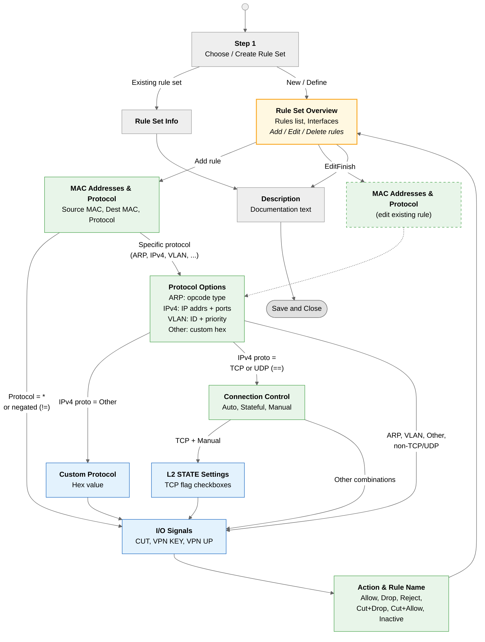
Choose or create a rule set

Select an existing predefined rule set or create a new one. Predefined rule sets provide common starting configurations. Predefined rule sets can be modified after copying them with the Copy button. A rule set may contain up to 10 filter rules.
Rule set overview

Displays all rules in the current rule set. From here, rules can be added, edited, reordered, or deleted. The interface selectors at the top define which source and destination interfaces this rule set applies to.
MAC addresses and protocol

Define the source and destination MAC addresses and select the Ethernet protocol for this rule.
- Source MAC address
- The source MAC address to match (format: XX:XX:XX:XX:XX:XX). Leave empty to match any source address. Hardware groups can be used instead of individual addresses.
- Use hardware groups
- When enabled, select a predefined hardware group instead of entering a MAC address manually. Hardware groups are defined on the Hardware groups page.
- Destination MAC address
- The destination MAC address to match. Same format as source address.
- Protocol
- The Ethernet protocol to match. Available options: * (any), ARP, IPV4, Vlan (802.1Q), Other. The selected protocol determines which additional options appear in the next wizard step. When * is selected, the protocol options step is skipped entirely.
Protocol options — ARP

This step appears when ARP is selected as the Ethernet protocol. Select the ARP opcode type to match — the most common types are Request and Reply.
Protocol options — IPv4

This step appears when IPV4 is selected as the Ethernet protocol. It provides a combined view for configuring IP addresses, subnet masks, and an optional transport protocol with port numbers — similar to the Layer 3 IP addresses and protocol and TCP/UDP ports steps.
- Source/Destination IP address/mask
- The source and destination IP addresses and subnet masks to match. Network groups can be used instead of individual addresses.
- IP protocol
- The transport protocol within IPv4. When TCP or UDP is selected, source and destination port fields appear. An additional Connection control step is shown for TCP/UDP rules.
- Source port / Destination port
- Port numbers to match (only visible when TCP or UDP is selected).
I/O signals
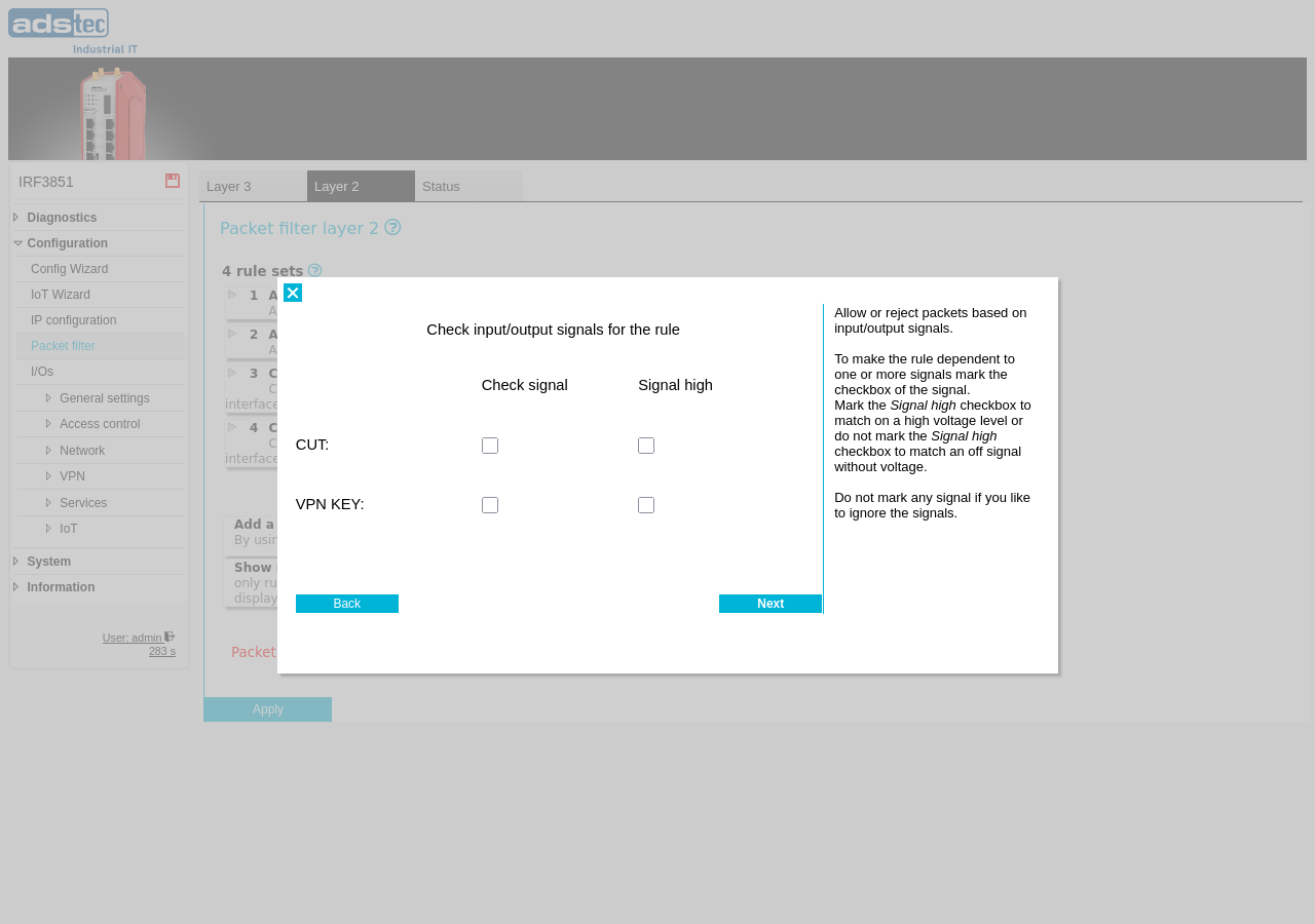
Allow or reject packets based on the state of the device's input/output signals. The available signals and options are the same as for the Layer 3 signals step.
Action and rule name
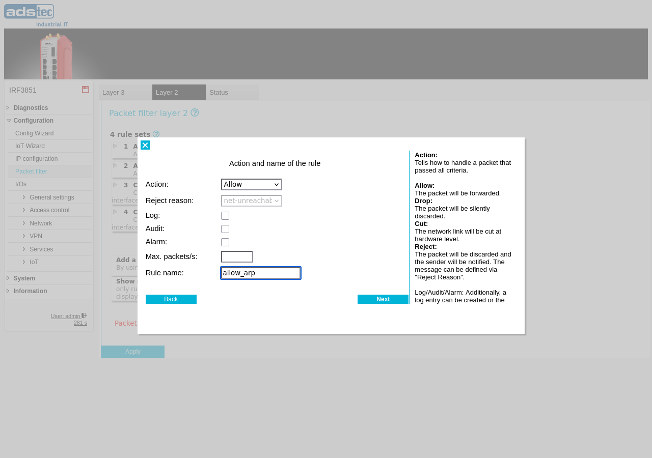
Define the action for packets matching this rule. The available actions and options are the same as for the Layer 3 action step.
Rule set description

Enter an optional description for the rule set. This text is used for documentation purposes only. This is the final step of the Layer 2 rule set wizard — the Layer 2 filter has no time-based activity scheduling.