System features
General LED status displays
The integrated LEDs indicate the status of the various interfaces. This makes diagnosis possible at the installation site.
| LED status | Representation |
|---|---|
| Off | |
| Illuminates green | |
| Flashes green | |
| Illuminates red | |
| Illuminates orange | |
| Flashes orange |
Front LEDs
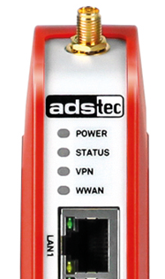
| LED | Signal | Action |
|---|---|---|
| Power | Device is not supplied with voltage. | |
| Voltage was switched on, device booting. LED flashes slowly (1 Hz). | ||
| Firmware is being updated. LED flashes rapidly (5 Hz). | ||
| The device is ready for operation. | ||
| Status | Device is not supplied with voltage. | |
| Device in commissioning mode | ||
| Error during the boot-up process / recovery image | ||
| VPN | No VPN tunnel is active. | |
| The tunnel activated via VPN key is active. | ||
| WWAN | No mobile radio connection active. | |
| Network search (1 Hz) | ||
| Login declined (2 Hz) | ||
| Firmware update of the radio module (5 Hz) | ||
| Logged in, offline | ||
| Logged in, standby (dial-on-demand) | ||
| Logged in, online | ||
| LANx / WAN | Link/activity | |
| Speed (down: 100 Mbit/s; up: 10 Mbit/s) |
Operating-related LED status displays
Behaviour of the status displays during the boot-up process
The boot-up process begins as soon as the device is supplied with power. The PWR-LED flashes slowly.
Behaviour of the status displays when resetting to default settings
The Factory Default button is used to reset the firewall back to the default factory settings at any time, independent of its configuration.
To reset the firewall to the default settings, the Factory Default button must be pressed prior to the boot-up process and held down for approx. 10 seconds during the boot-up process. The PWR LED flashes rapidly while resetting to factory settings. As soon as the PWR LED illuminates constantly, it is possible to access the web interface.
Behaviour of the status displays during the firmware update
A firmware update can be performed via the web interface.
-
The PWR-LED flashes rapidly during a firmware update of the firewall. The actual update procedure takes a few minutes. Initialisation begins after the update procedure has been performed successfully. The PWR-LED flashes slowly during this process.
-
During a firmware update of the mobile radio module, the yellow WWAN-LED flashes with a frequency of 5 Hz.
Interface overview
24 VDC power supply
Power is fed to the device via a lead-through terminal (figure shows connector on the device).
| Pin | Signal |
|---|---|
| DI | 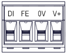 Digital input +24 VDC ± 20 % Digital input +24 VDC ± 20 %(function configurable) |
| FE |  Functional earth (required for EMC) Functional earth (required for EMC) |
| 0V | Reference potential 0 V |
| V+ | Supply voltage +24 VDC ± 20 % |
Requirements on the power supply
-
Conformity: > - Class PS2 acc. to IEC 62368-1 or > - Limited Power Source (LPS) acc. to IEC 60950-1 > - For devices with UL-Certification: NEC Class 2
-
Voltage: 24 VDC ± 20 %
-
Short-circuit current: \< 8 A
Informations on using the device acc. to UL certification (Underwriter Laboratories, USA):
-
For the power supply of the device, a power adapter acc. to NEC Class 2 must be used (LPS = Limited Power Source).
-
Only use copper conductors to connect the power supply.
Recommendation for use
Recommendation for use: Use flexible cables with a wire cross section of 0.5 mm² / AWG20 and appropriate cable end sleeves. To minimise mechanical strain between the individual wires and the plug, the distance between jacket and plug should be at least 30 mm.
RS-485 (EIA-485) for Modbus RTU
The fieldbus node is electrically isolated from the power supply of the IRF.
Its electrical bus load is 1/8 unit load.
| Pin | Signal |
|---|---|
| GND | Reference potential (common) for the data signals |
| D- | Inverted data signal |
| D+ | Non-inverted data signal |
Smart card reader and slot for SIM card
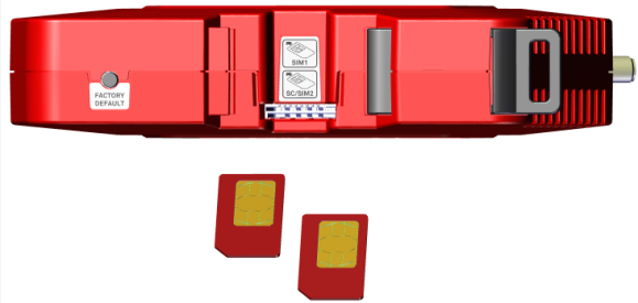
SIM cards and smart cards (SC) in the ID-000 format as defined in ISO 7816 (25x15 mm) can be used.
-
The SIM card for mobile communications must be inserted into the top slot (SIM1).
-
The smart card is intended for backing up the configuration data or for connecting to Big-LinX® and must be inserted into the bottom slot.
Insert the card(s) into the dual slot the right way round as shown in the figure:
Recommendation for use
The configuration data of a device can be stored on the smart card. If service is required, the saved configuration can be transferred to the new device. The setup procedure does not need to be repeated.
Recommendation for use
Complex IT infrastructures with a large number of devices can be managed, monitored and controlled easily and conveniently using Big-LinX®. Further information on Big-LinX can be found at: http://www.ads-tec.de/industrial-it/cloud-big-linx/big-linx.html